This project aims to create a simple sound player which triggers whenever a door has been opened to play some fun introduction sounds. It’s based on a Raspberry Pi, a magnetic switch and some other low-cost and accessible hardware pieces. Of course, anyone could go ahead and buy something mass produced, but it’s always more fun to build stuff yourself.I got the idea a while back from seeing a YouTube video where this guy had created a custom door opening sensor that would play the iconic bass riffs from Seinfeld whenever the door opened. Seeing as how I love technology I figured it would make a good addition to my office, so I built an enhanced version. This is the resulting project.
This project was developed in partnership with Conrad in their efforts to showcase makers around Sweden. I would therefore like to thank them for providing the hardware used in this project. Please also check out their website for more interesting projects.
Just as the last one, this project is very straight forward, requiring only parts that you can plug and play combined with a basic knowledge of Raspberry Pi and Linux. The products required are listed below:
- Raspberry Pi (Model 3 recommended because of Wi-Fi)
Click here to view product at Conrad.se
- Micro-USB cable for Raspberry Pi power
Click here to view product at Conrad.se
- SD Card for the Raspberry Pi
Click here to view product at Conrad.se
- USB Power Supply for Raspberry Pi and speaker
Click here to view product at Conrad.se
- Mini speaker with good sound (JBL Go)
Click here to view product at Conrad.se
- 3.5mm speaker cable (angled connector)
Click here to view product at Conrad.se
- Magnetic switch (Normally open)
Click here to view product at Conrad.se
Since I wanted to make my build somewhat fancy, I created a design to encapsulate the electronics which I then printed with my 3D-printer. Do note that this is definitely not a requirement to make this project work. The files are public and can be used by anyone (please send me a picture if you do print it). In order to print it and mount everything properly, you will also need the following products:
- 3D-Printing filament (I used this Renkforce PLA)
Click here to view product at Conrad.se
- IEC C14 power cord inlet
Click here to view product at Conrad.se
- IEC C13 power cord
Click here to view product at Conrad.se
- 250V power cord plug
Click here to view product at Conrad.se
Those are the products needed, and while I recommend the above products due to compatibility with my case, any Raspberry Pi and speaker could potentially be used for this. Also, the following steps assume that you have access to basic tools such as a high voltage cables, soldering iron and other minor things.
1. Initial Raspberry Pi configuration
Download the latest Raspbian operating system and install that to the Raspberry Pi SD-card. Once it’s installed, try starting the Raspberry Pi with a monitor connected to make sure the system works like intended. The operating system already includes everything that we need, so no work there. If you don’t know how to put the system on the SD-card, please refer to this guide. If everything works as intended you can go ahead and shut it down for now. We will continue with the software shortly.
2. Expand the root partition size (optional and not needed)
By default the root partition on the SD-card is very small leaving limited space for storing our audio files. If you won’t store a whole lot of audio files on your build then you can absolutely skip this step, but I prefer to have it done in any case so that my Raspberry is ready should I need the space. You use the command sudo raspi-config to initiate the following screen. Once done, select Finish and let it reboot your Raspberry Pi. Once that’s done you should be all set. Keep in mind that on newer versions of Raspbian, this is done automatically upon the first boot.

3. Hook up the speaker and set the volume
Connect the speaker to the power supply and also to the Raspberry Pi with the 3.5mm audio cable. This is just in preparation for the next steps, but it’s good to have it done so that you’re ready to test the audio once we try out the software. You can use the command sudo alsamixer to control the master volume on the device. I usually leave it around 60-70, but it comes down to the speaker volume as well, so experiment until you find an ideal percentage.
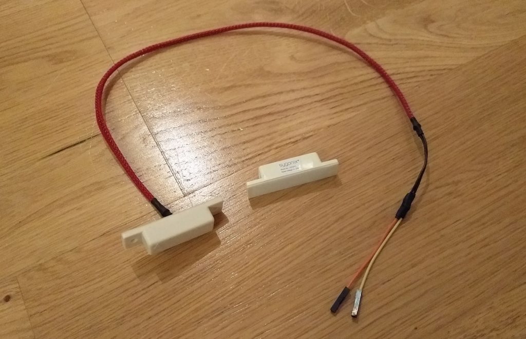
4. Wire the magnetic switch and connect it to the Raspberry Pi
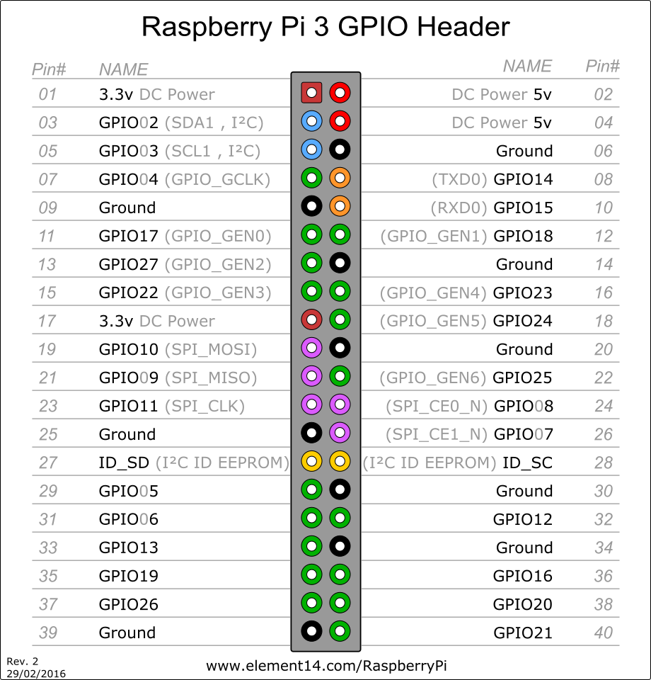
The magnetic switch is a normally open switch, this means that the circuit is open until the switch comes in contact with the other side. Once it loses contact and goes back to it’s default state, we execute the code that triggers the audio. All you need to get this working is to connect two cables between the Raspberry Pi and the main part of the magnetic switch. I went the extra mile and soldered some long cables which I then sleeved so that they would look better, but anything goes really. Mine are connected to GPIO23 on pin 16 and ground on pin 20. You can alter these however you want, but the software has been pre-configured to run off GPIO23. See the schematic below for more information on which pin is which.
5. Create the correct directories and upload the software
The software was written by me for this specific project. It’s a simple Python application which listens for the sensor to signal that the door has been opened. It has support for multiple soundpacks, and you can add your own by simply creating a subdirectory in the directory called soundpacks and upload the files there. The sound files need to be in the format of WAV to properly play. Anything else will not work and possible also crash the software.
Once logged in to your Raspberry, go to the home directory by using the command cd and then execute the command listed below. As the code is hosted on GitHub you can just clone it and do a pull to get the latest updates, should you have any problems.
git clone https://github.com/jonathanlundstrom/door-sensor-soundbox.git Applications/DoorSensor
The path to the main file should now be ~/home/pi/Applications/DoorSensor/sensor.py.
6. Install application dependencies
The application depends on a Python library called ConfigParser in order to read the configuration file. If you do not have this installed the application won’t start and you’ll be presented with an error. To install this, please enter the following command and you’re good to go.
sudo pip install configparser
7. Configure and start the software for the first time
If you paid attention to the files that were uploaded then you probably saw the file config.ini. This is the configuration file for the application and it contains options such as volume, fadeout time, selected soudpack and some feature sounds. The soundpacks that I’ve included are Seinfeld, Arnold Schwarzenegger, Star Wars and a separate Imperial March. Should there be any errors in the configuration, such as setting a soundpack which does not exist, an error message will play whenever the door is opened. Look below for an overview of the configuration lines:
- gpio_pin – The pin that should be used (23 = pin #16)
- volume – The volume level, use 1.0 to use system volume.
- fadeout – The time in milliseconds during which a clip fades out.
- soundpack – The selected soundpack, name of the subdirectory with WAV-files.
- sound_on_start – Whether or not to play a sound on start (True/False)
- sound_on_exit – Whether or not to play a sound on exiting (True/False)
Once you’ve configured everything, you should be able to run the software by typing python sensor.py. Make sure you are inside the correct directory while running the command, otherwise you’ll just get an error. To exit, press CTRL + C. If the switch is wired correctly and your configuration is valid then everything should work at this point. Good job!
This is the last official step should you not wish to carry on with the 3D-printing. If so, please continue reading.
8. Configure the software to autostart and stay alive (Optional)
Applications don’t normally start by themselves, hence the need for a piece of software called Supervisor. It’s a simple python application that allows us to create a job that will start the software when the Raspberry Pi starts, and restart it should anything go wrong. Install supervisor by typing in the following command: sudo apt-get install supervisor. Once that finishes Supervisor is installed and you’re ready to create the autostart job.
The supervisor config should be placed in /etc/supervisor/conf.d/ and named sensor.conf or similar. Restarting Supervisor with the following command should trigger the software: sudo service supervisor restart
[program:sensor]

directory=/home/pi/Applications/DoorSensor

command=python sensor.py

autostart=true

autorestart=true

stderr_logfile=/var/log/sensor.err.log

stdout_logfile=/var/log/sensor.out.log
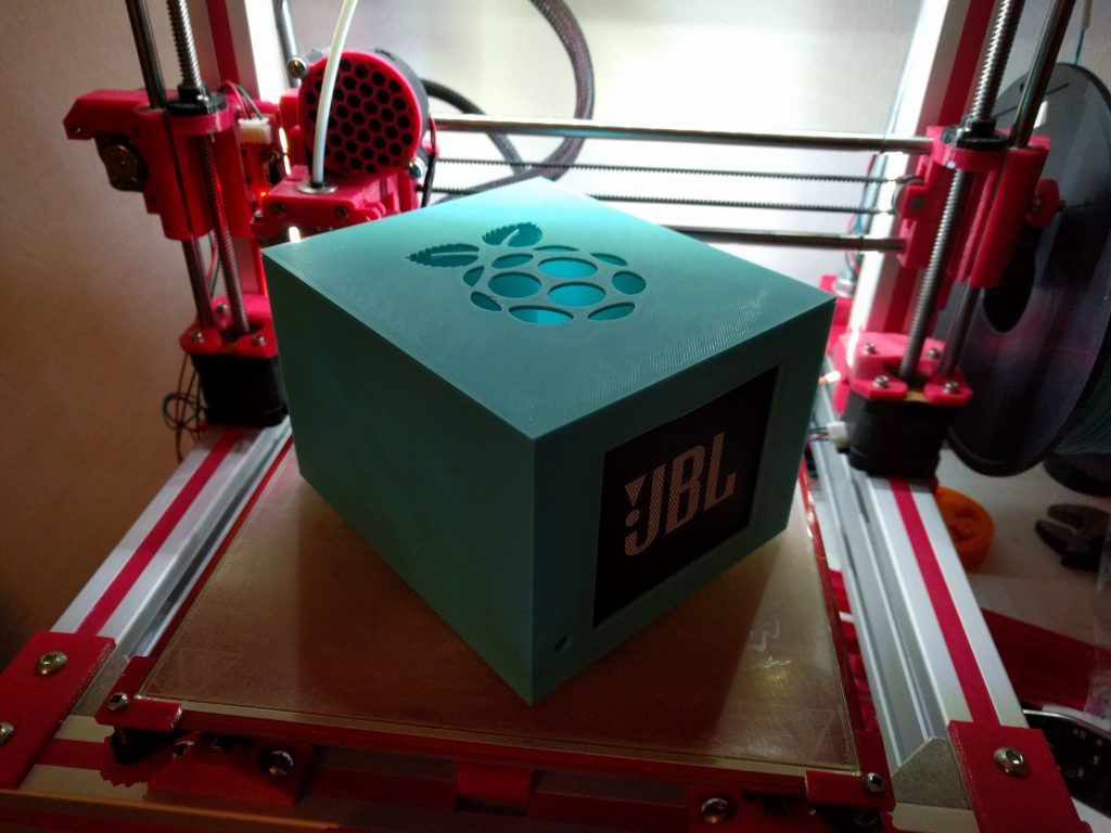
9. Print the enclosure to make your project look pretty (Optional)
To make it easy to maintain I’ve uploaded the case design to Thingiverse. It includes two files, one for the bottom and one for the top. The walls are 1.6mm thick so I recommend you use a 0.4mm nozzle and print all pieces at 100% infill with 4 perimeters. The bottom case should print in about 10-12 hours and the lid is another 2-3 hours. If you decide to print one, please upload some images to the make section on Thingiverse. The case is optimized for the C14 inlet, the JBL Go speaker and a Raspberry Pi 3, anything else will not fit. Also, it’s designed with high precision and near zero tolerance, so your results may vary compared to mine.
10. Putting it all together (Optional)
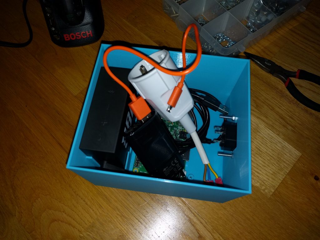
Once you’ve got everything printed it’s time to wire the C14 inlet and the power cord plug. Since we’re working with AC (~250V) I urge you to take great caution. Please refrain from touching any live wires as this could be potentially lethal. You can see how I’ve wired mine in the following image.
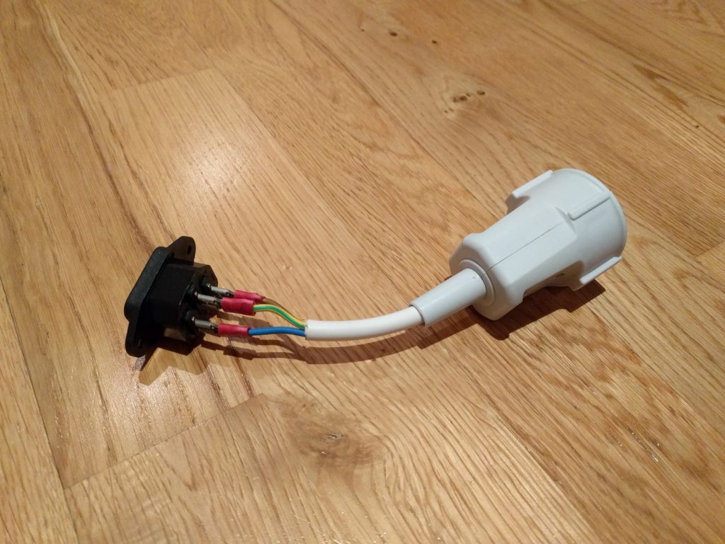
The C14 inlet is attached to the case with two M3 screws and accompanying M3 nuts. The Raspberry Pi should most likely be mounted with M2.5 screws, but it works with M3 as well, and that’s what I’ve designed the case to accept. As you can see from the image below it gets pretty cramped in there, but the parts all actually fit in there with room to attach the lid. The lid is designed with 0.2mm clearance and should be a press fit.
Here’s what the finished product looks like
Source code on GitHub:
https://github.com/jonathanlundstrom/door-sensor-soundbox
Case model on Thingiverse:
http://www.thingiverse.com/thing:2140581
Things other people recently wrote